01 / INTEGRATED MODELThe full
The full
project picture.
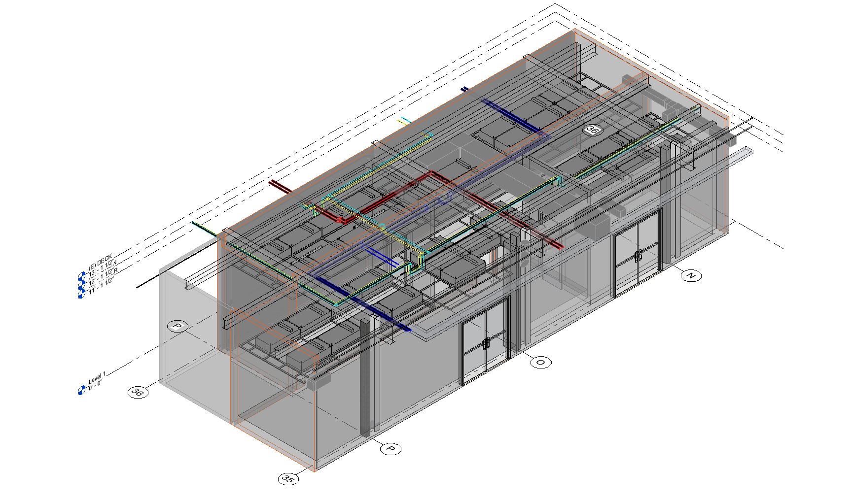
A coordinated architectural and equipment model provided a common spatial reference for the GC and trade partners, supporting layout decisions and constructability reviews.
 TECHNICALABCONSTRUCTION TECHNOLOGYRequest a Quote
PROJECT 02 / BIM + VDC
Coordinating complex overhead systems and laboratory equipment before construction begins.
PROJECT OVERVIEW
This laboratory tenant improvement project required precise coordination of overhead building systems, specialized equipment, and architectural components to meet demanding client and engineering requirements.
A central challenge was the integration of a rigid suspended ceiling grid with precisely positioned filtration units, where installation tolerances and equipment clearances required careful planning.
TechnicaLab collaborated with the general contractor and trade subcontractors to develop and coordinate the building information model, evaluate equipment fitment, and visualize critical construction conditions before field mobilization.
Through early BIM/VDC implementation, the project team was able to identify potential conflicts, resolve coordination challenges, and support an efficient construction sequence—reducing the risk of field rework and schedule disruptions.
PROJECT DELIVERY
TechnicaLab self-performed BIM/VDC coordination, equipment-layout studies, and visualization in partnership with the general contractor and trade team. This scope was limited to non-stamped coordination and visualization services; architectural or engineering documents requiring professional licensure remained outside TechnicaLab’s scope.
COORDINATION WORKFLOW
A coordinated architectural and equipment model provided a common spatial reference for the GC and trade partners, supporting layout decisions and constructability reviews.
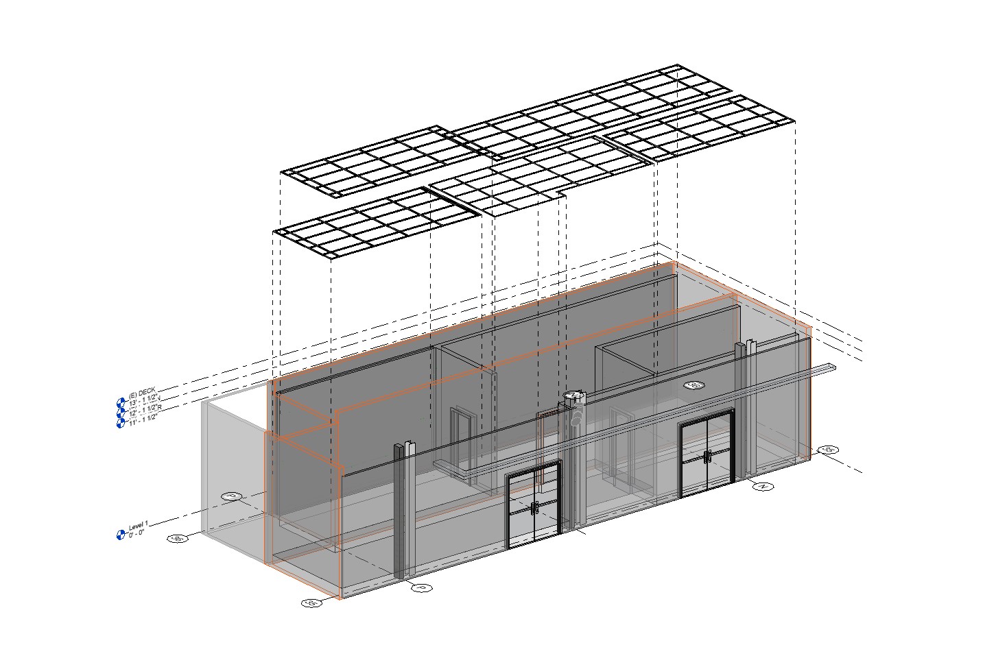
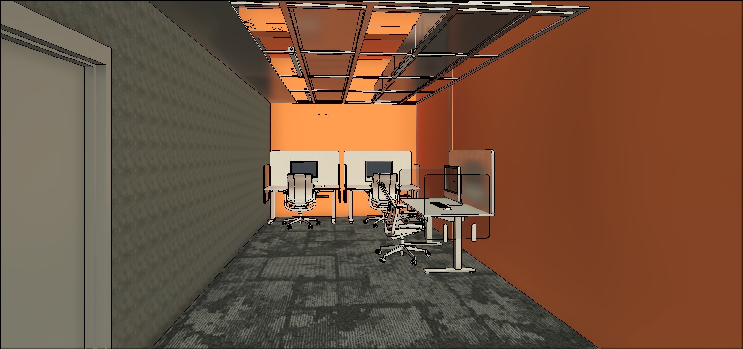
The suspended ceiling grid was evaluated in relation to the room geometry and required overhead components, helping the team plan precise filter-unit locations.
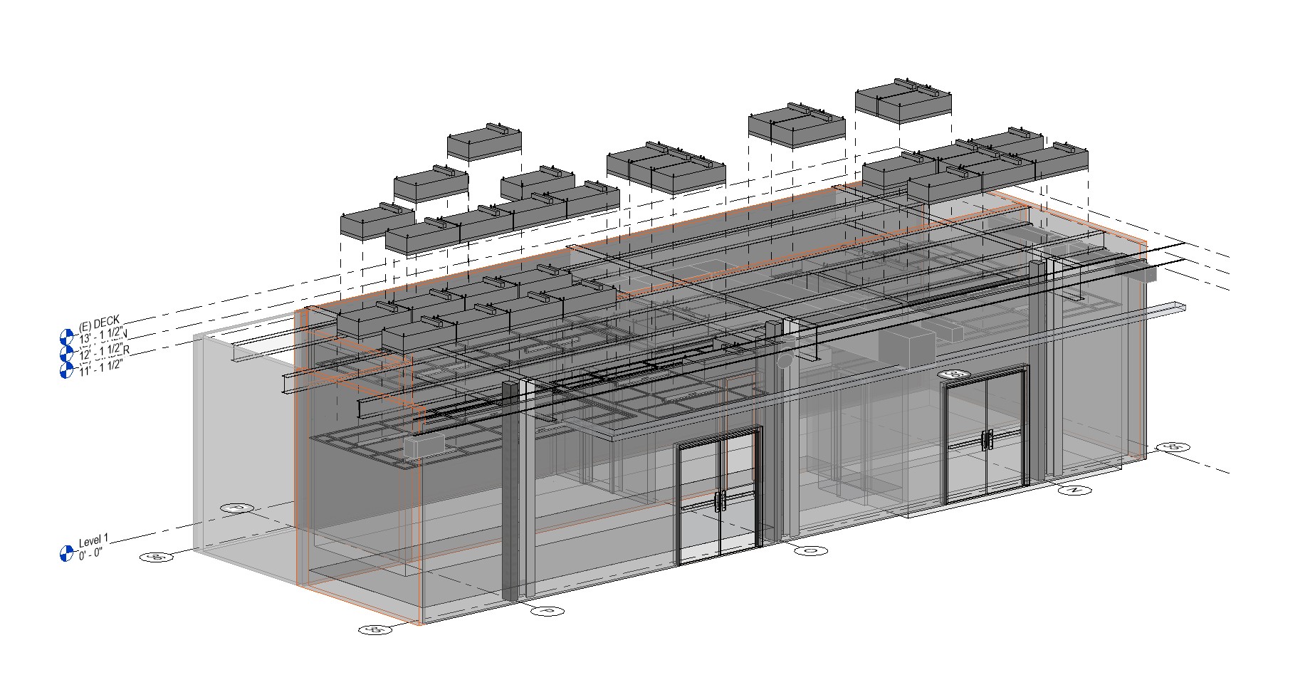
An exploded view of ceiling-mounted equipment illustrates the dense overhead conditions and supports review of clearances, installation zones and alignment.
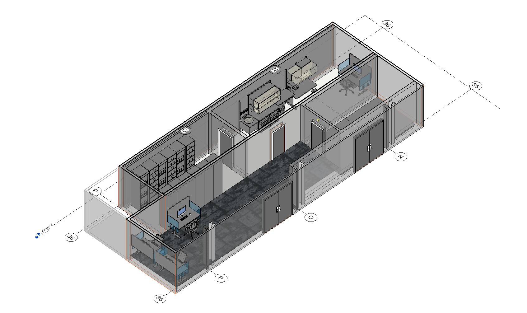
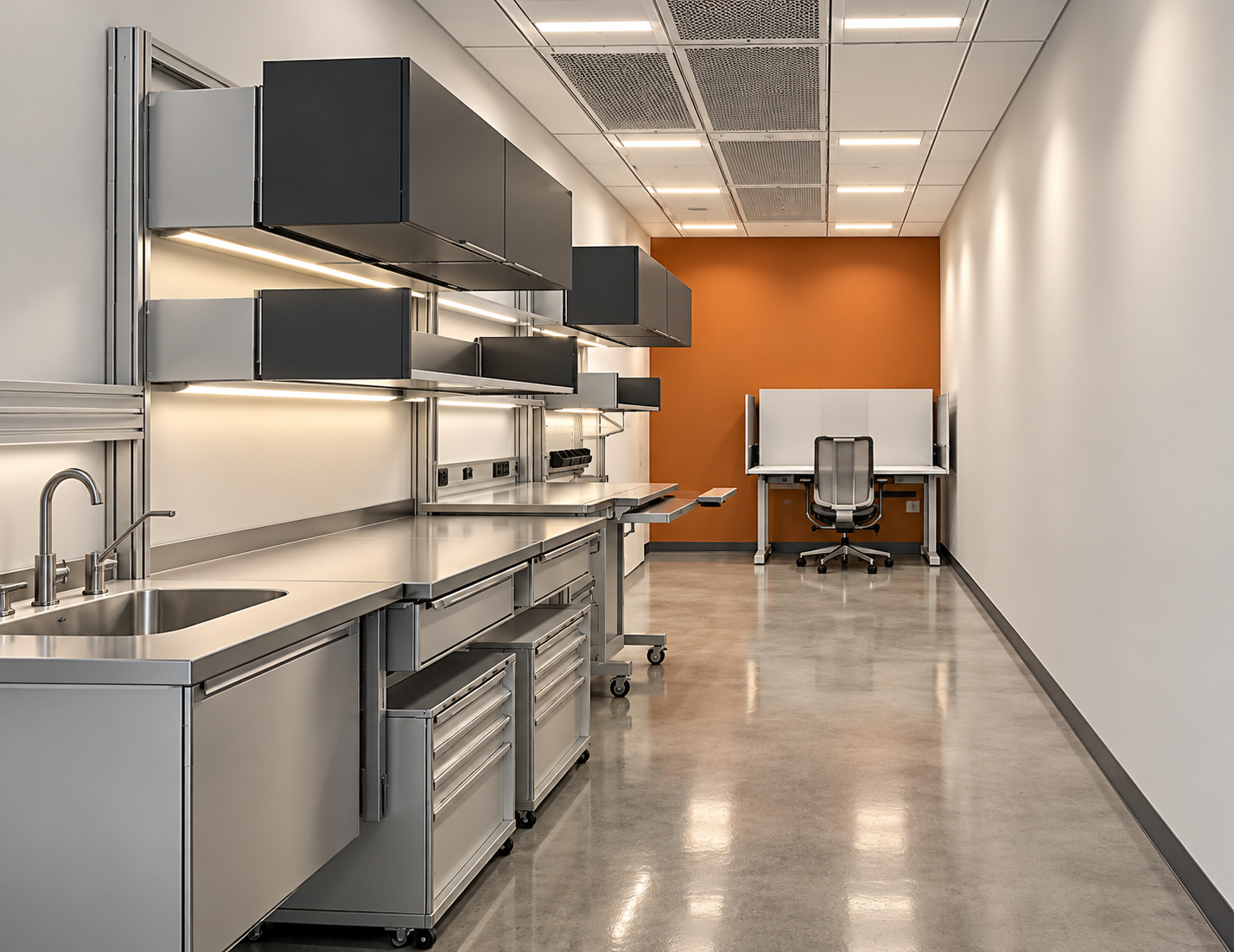
Workstations, lab casework and other equipment were modeled to review the fit of the intended interior program alongside building systems.
PROJECT VISUALIZATION
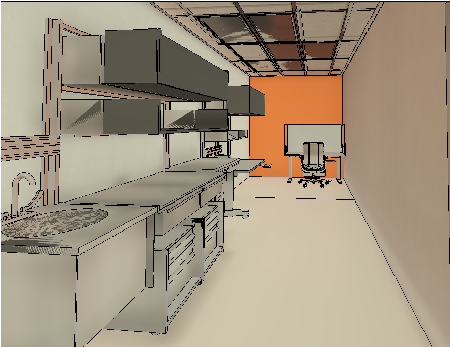
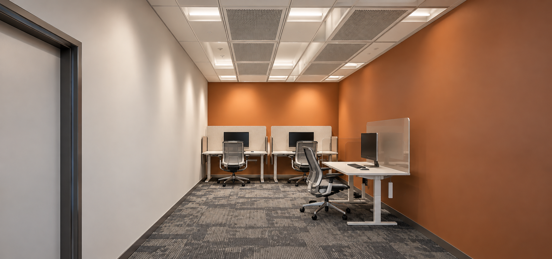
Conceptual renderings illustrate the intended material palette and finished space. The paired source views show the underlying design model; renderings are illustrative, not photographs of completed construction.
COORDINATE BEFORE YOU BUILD
Planning a laboratory or technically demanding interior build-out? Let's discuss BIM coordination, equipment layout and project visualization.